


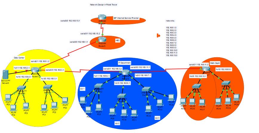
In this tutorial, We will talk about different lab configurations like RIP, OSPF, Access-list, static routing, and VLAN.
Configuration of RIP:
Steps:
- Click on the router and go to CLI.
- Type the following commands.
- enable To go to privilege mode
- config t Command to go to the configuration mode
- router rip
- the network network address (Enter all the network addresses)
Repeat step number 5 and 6 on all the routers in your network.
OSPF Configuration
Following are the steps to configure OSPF:
- Click on the Router and go to CLI.
- enable
- Config t
- router OSPF 1
- network network address wildcard mask area 0
Do these steps on each router
Access List Configuration:
An access list is used to block a single host or block a hole network.
Steps to Block Single User:
- Click on router
- enable
- config t
- access-list 1 deny host hostip
- access-list 1 permit any
- Go to interface toward blocking pc or network like
- interface fa0/0
- IP access-group 1 out
Steps to block the whole network:
Following are the steps to block the whole network
Steps:
- enable
- config t
- access -list 2 deny network wildcard mask
- access – list 2 permit any
- go to interface like fa0/0
- ip access-group 2 out
Static routing Configuration
Following are the steps to configure static routing.
Steps:
- enable
- config t
- IP route network Address SubnetMask NextHopeIp
VLAN Configuration:
Following are the steps to configure Vlan;
configuration on Switch:
- enable
- config t
- vlan 2
- name Lab1
- exit
- vlan 3
- name Lab2
- exit
- Vlan 4
- name Lab3
- exit
- interface fa0/0
- switchport mode trunk
- exit
- interface fa0/1
- switchport mode access
- switchport access vlan 2
- exit
- interface fa0/2
- switchport mode access
- switchport access vlan 2
- exit
- interface fa0/3
- switchport mode access
- switchport mode access vlan 3
- exit
- interface fa0/4
- switchport mode access
- switchport access vlan 3
- exit
- interface fa0/5
- switchport mode access
- switchport access vlan 4
- exit
- interface fa0/6
- switchport mode access
- switchport access vlan 4
- exit
Configuration on the router
Now click on attached router and go to cli.
- enable
- config t
- interface fa0/8
- no ip address
- no shutdown
Now Go to vertual interfaces:
- interface fa0/8.2
- ip address 192.168.1.1 255.255.255.0
- encapsulation dot1q 2
- exit
- interface fa0/8.3
- ip address 192.168.2.1 255.255.255.0
- encapsulation dot1q 3
- exit
- interface fa0/8.4
- ip address 192.168.3.1 255.255.255.0
- encapsulation dot1q3
- exit